3.4 KiB
Chain Sprockets ISO606 duplex 1/2" x 5/16" from z 8 to z 114
This folder contains the 3D models of the sprockets for ISO 606 chains duplex 1/2" x 5/16" with number of teeth ranging from z=8 to z=114.

The model is parametric and the values are contained in the spreadsheet Data.
The parameters refer to the sprocket dimensions as in the drawing below:

Table of dimensions in millimeters:
| P (Pitch) | Wc (Chain width) | Dr (Roller diameter) | Tr (Tooth radius) | Rw (Radius width) | Wt1 (Tooth width 1) | Wt2 (Tooth width 2) | z (Number of teeth) | De (External Diameter) | Dp (pitch diameter) | d (Hub diameter) | D (Hole diameter) | H (Total height) |
|---|---|---|---|---|---|---|---|---|---|---|---|---|
| 12,7 | 7,75 | 8,51 | 13 | 1,3 | 7 | 21 | 8 | 37 | 33,18 | 20 | 10 | 32 |
| 12,7 | 7,75 | 8,51 | 13 | 1,3 | 7 | 21 | 9 | 41 | 37,13 | 24 | 10 | 32 |
| 12,7 | 7,75 | 8,51 | 13 | 1,3 | 7 | 21 | 10 | 45,2 | 41,1 | 28 | 10 | 32 |
| 12,7 | 7,75 | 8,51 | 13 | 1,3 | 7 | 21 | 11 | 48,7 | 45,07 | 32 | 12 | 35 |
| 12,7 | 7,75 | 8,51 | 13 | 1,3 | 7 | 21 | 12 | 53 | 49,07 | 35 | 12 | 35 |
| 12,7 | 7,75 | 8,51 | 13 | 1,3 | 7 | 21 | 13 | 57,4 | 53,06 | 38 | 12 | 35 |
| 12,7 | 7,75 | 8,51 | 13 | 1,3 | 7 | 21 | 14 | 61,8 | 57,07 | 42 | 12 | 35 |
| 12,7 | 7,75 | 8,51 | 13 | 1,3 | 7 | 21 | 15 | 65,5 | 61,09 | 46 | 12 | 35 |
| 12,7 | 7,75 | 8,51 | 13 | 1,3 | 7 | 21 | 16 | 69,5 | 65,1 | 50 | 14 | 35 |
| 12,7 | 7,75 | 8,51 | 13 | 1,3 | 7 | 21 | 17 | 73,6 | 69,11 | 54 | 14 | 35 |
| 12,7 | 7,75 | 8,51 | 13 | 1,3 | 7 | 21 | 18 | 77,8 | 73,14 | 58 | 14 | 35 |
| 12,7 | 7,75 | 8,51 | 13 | 1,3 | 7 | 21 | 19 | 81,7 | 77,16 | 62 | 14 | 35 |
| 12,7 | 7,75 | 8,51 | 13 | 1,3 | 7 | 21 | 20 | 85,8 | 81,19 | 66 | 14 | 35 |
| 12,7 | 7,75 | 8,51 | 13 | 1,3 | 7 | 21 | 21 | 89,7 | 85,22 | 70 | 16 | 40 |
| 12,7 | 7,75 | 8,51 | 13 | 1,3 | 7 | 21 | 22 | 93,8 | 89,24 | 70 | 16 | 40 |
| 12,7 | 7,75 | 8,51 | 13 | 1,3 | 7 | 21 | 23 | 98,2 | 93,27 | 70 | 16 | 40 |
| 12,7 | 7,75 | 8,51 | 13 | 1,3 | 7 | 21 | 24 | 101,8 | 97,29 | 75 | 16 | 40 |
| 12,7 | 7,75 | 8,51 | 13 | 1,3 | 7 | 21 | 25 | 105,8 | 101,33 | 80 | 16 | 40 |
| 12,7 | 7,75 | 8,51 | 13 | 1,3 | 7 | 21 | 26 | 110 | 105,36 | 85 | 16 | 40 |
| 12,7 | 7,75 | 8,51 | 13 | 1,3 | 7 | 21 | 27 | 114 | 109,4 | 85 | 16 | 40 |
| 12,7 | 7,75 | 8,51 | 13 | 1,3 | 7 | 21 | 28 | 118 | 113,42 | 90 | 16 | 40 |
| 12,7 | 7,75 | 8,51 | 13 | 1,3 | 7 | 21 | 29 | 122 | 117,46 | 95 | 16 | 40 |
| 12,7 | 7,75 | 8,51 | 13 | 1,3 | 7 | 21 | 30 | 126,1 | 121,5 | 100 | 16 | 40 |
| 12,7 | 7,75 | 8,51 | 13 | 1,3 | 7 | 21 | 31 | 130,2 | 125,54 | 100 | 20 | 40 |
| 12,7 | 7,75 | 8,51 | 13 | 1,3 | 7 | 21 | 32 | 134,3 | 129,56 | 100 | 20 | 40 |
| 12,7 | 7,75 | 8,51 | 13 | 1,3 | 7 | 21 | 33 | 138,4 | 133,6 | 100 | 20 | 40 |
| 12,7 | 7,75 | 8,51 | 13 | 1,3 | 7 | 21 | 34 | 142,6 | 137,64 | 100 | 20 | 40 |
| 12,7 | 7,75 | 8,51 | 13 | 1,3 | 7 | 21 | 35 | 146,7 | 141,68 | 100 | 20 | 40 |
| 12,7 | 7,75 | 8,51 | 13 | 1,3 | 7 | 21 | 36 | 151 | 145,72 | 100 | 20 | 40 |
| 12,7 | 7,75 | 8,51 | 13 | 1,3 | 7 | 21 | 37 | 154,6 | 149,76 | 100 | 20 | 40 |
| 12,7 | 7,75 | 8,51 | 13 | 1,3 | 7 | 21 | 38 | 158,6 | 153,8 | 100 | 20 | 40 |
| 12,7 | 7,75 | 8,51 | 13 | 1,3 | 7 | 21 | 39 | 162,7 | 157,83 | 100 | 20 | 40 |
| 12,7 | 7,75 | 8,51 | 13 | 1,3 | 7 | 21 | 40 | 166,8 | 161,87 | 100 | 20 | 40 |
| 12,7 | 7,75 | 8,51 | 13 | 1,3 | 7 | 21 | 45 | 188 | 182,07 | 108 | 20 | 50 |
| 12,7 | 7,75 | 8,51 | 13 | 1,3 | 7 | 21 | 50 | 208,3 | 202,26 | 108 | 20 | 50 |
| 12,7 | 7,75 | 8,51 | 13 | 1,3 | 7 | 21 | 57 | 236,4 | 230,54 | 108 | 20 | 50 |
| 12,7 | 7,75 | 8,51 | 13 | 1,3 | 7 | 21 | 76 | 313,3 | 307,32 | 108 | 20 | 55 |
| 12,7 | 7,75 | 8,51 | 13 | 1,3 | 7 | 21 | 95 | 390,1 | 384,11 | 110 | 20 | 55 |
| 12,7 | 7,75 | 8,51 | 13 | 1,3 | 7 | 21 | 114 | 466,9 | 460,91 | 110 | 20 | 55 |
The 3D model configuration of each sprocket can be dynamically retrieved using a preset Configuration table.
The file name of the 3D model containing the Configuration table is Sprocket ANSI duplex ½x⁵⁄₁₆.FCStd.
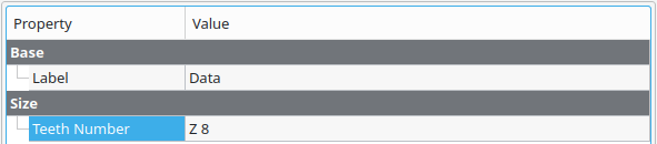
To obtain the 3D model of the desidered sprocket, click the spreadsheet Data in the Tree View and then select the Teeth Number in the property editor. If nothing changes try to Refresh the model.
See the following image for details
Notes for developers
If you add a row in the Configuration table of the Data spreadsheet, then add that row in the above table of this README.md file, without the first cell.